|
The Box
 My original oven was smaller than I liked. Ideally, all of the light from the 18" x 18" reflector panels will pass
through the tempered glass collector plate into the interior of the oven. (My glass collector plate is slightly
larger than the reflectors: 18-1/2" x 18-1/8".)
My original oven was smaller than I liked. Ideally, all of the light from the 18" x 18" reflector panels will pass
through the tempered glass collector plate into the interior of the oven. (My glass collector plate is slightly
larger than the reflectors: 18-1/2" x 18-1/8".)
But, in my original, the
collector plate also covered the full 1-1/2" insulation on each side, reducing the effective collector area to 15" x 15". Here,
I enlarged the interior by about 3" in each direction so as to capture almost all of the sunlight that hit the reflectors.
Unfortunately, this "enhancement" complicates construction, because with the reflectors being significantly offset
from the sides of the box, it is not so easy to use the sides for support.
I also deepened the box. The box needs to be tilted either forward or back so as to keep the collector plate sqaurely
facing the sun as it rises and sets through the day. (I will call the
untilted position, namely when the bottom of the box is level, the "horizontal" position.)
A gimballed tray
will keep the pot level, but both the pot width and height limit the angle through which the box can be tilted before the pot hits the
collector plate (morning tilt), or the liner back wall (noon tilt) A deeper box will extend the tilt range, thus capturing more rays over the
day.
The sides of the box are 9/16" scrap plywood I had laying around. The angle of the collector is 60 degrees
off the vertical, which makes for simpler cuts, simpler construction, and an oven which will serve at a
fairly wide range of latitudes. The angle between the reflectors and the collector plate will be 120 degrees (30 degrees off
the normal to the collector), which sends any ray normal to the collector plate into
the oven interior, as shown here:
|
 This 120-degree reflector angle is also the optimum angle; a larger angle will reflect many rays
away from the collector, whereas a lesser angle will reduce the effective area of the reflector itself.
This 120-degree reflector angle is also the optimum angle; a larger angle will reflect many rays
away from the collector, whereas a lesser angle will reduce the effective area of the reflector itself.
(To see this, imagine how the reflector would look from the sun. At 90 degrees off the normal, the reflector
would look like the square it is, and all rays would be reflected back into space.
At 5 degrees off the normal, say, all rays
hitting the reflector would be sent to the oven, but the effective reflector surface would be a 18" x 1.569"
strip instead of the optimal 18" x 9".)
I have
not bothered to figure out which of these errors is the worse one as regards wattage loss.
|
|
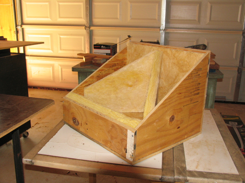
The insulation panels are cut from 2' x 4' x 1-1/2" pure fiberglass bats. These bats have no resinous bonding material on the fibers,
so they are fragile and need to be handled carefully. I'm pretty sure that standard fiberglass construction insulation is resin-bonded to
some degree, and I wanted an insulating material that would not
cook off toxic fumes in the 400+ degree temperatures
I expect the oven to attain. Unfortunately, I no longer have the name of the company that
sold me this insulation, or the brand name of the insulation itself. The labels disappeared long ago.
|
|
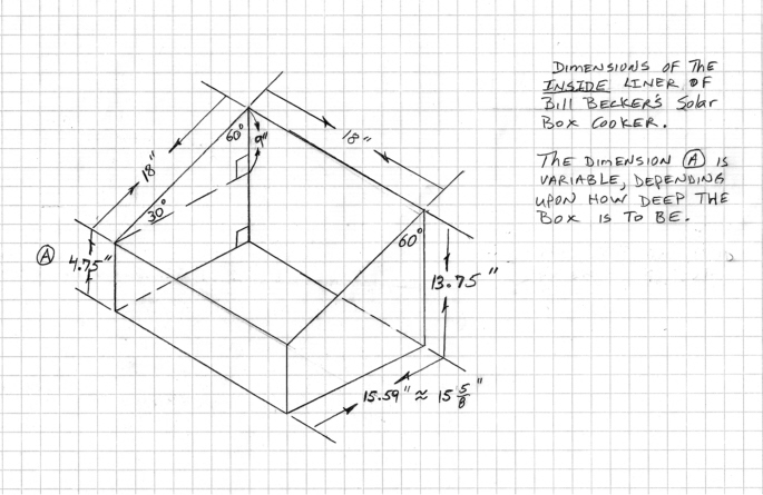 A diagram showing the dimensions of the inside liner box to be constructed as shown below.
|
|
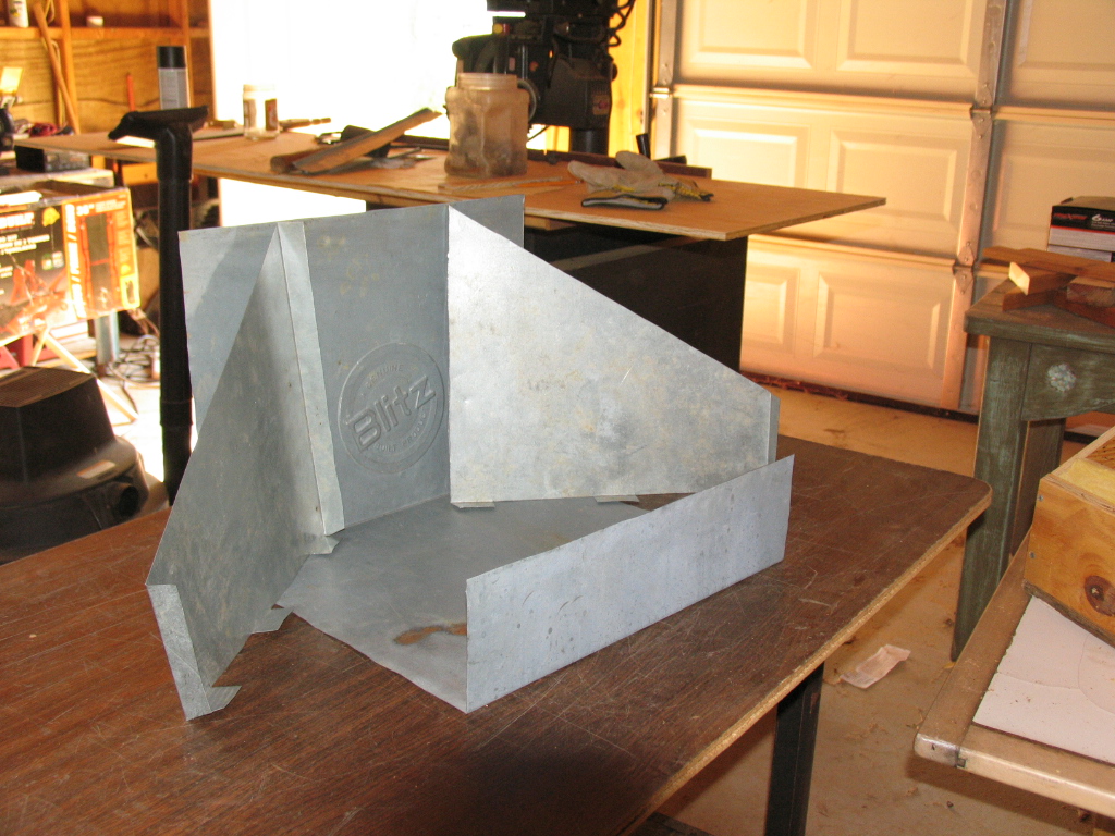 My original oven had a thin sheetmetal liner, and I repeated that design here. I figure that the metal radiates heat
back into the cooking volume more efficiently. I generally use an oil drip pan I buy from the local
auto parts store. I cut the pieces to shape with an aircraft shear, and bend them to fit the box.
The idea is self-evident here.
My original oven had a thin sheetmetal liner, and I repeated that design here. I figure that the metal radiates heat
back into the cooking volume more efficiently. I generally use an oil drip pan I buy from the local
auto parts store. I cut the pieces to shape with an aircraft shear, and bend them to fit the box.
The idea is self-evident here.
Each side piece will be screwed to the center section using sheet metal screws from a
small utility shed I dismantled. The heads of the screws will be on the outside of the liner
so as not to shred the insulation with the sharp points of the screws, which extend through the two layers
of sheet metal by about 1/4". I decided to re-use the screws rather than braze the liner sections together,
so as to reduce the energy used to make the oven itself. The inside surface of the fabricated liner will be spray-painted
flat black with Rustoleum high-temperature barbecue paint.
I should probably mention that the logo stamped on the back of the liner, "Blitz" is a registered trademark of some
company or another that makes oilpans.
|
|
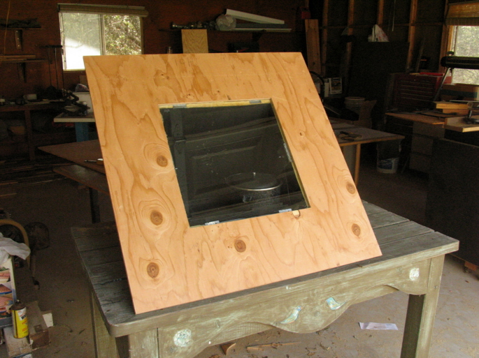
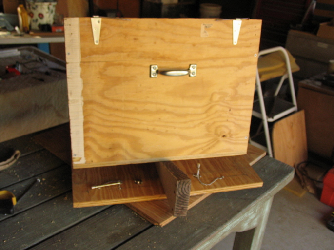
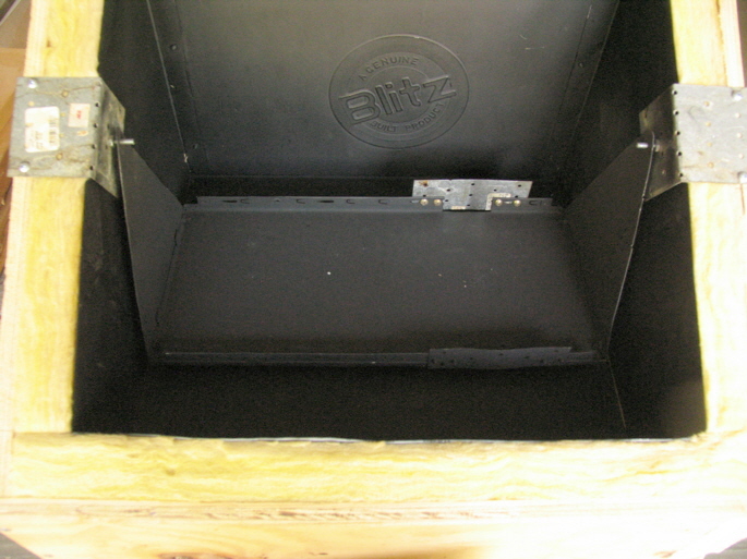 Several steps have been completed. The liner pieces have been screwed together, the interior has been
painted flat black, and the liner carefully installed into the box so as not to damage the insulation bats.
Several steps have been completed. The liner pieces have been screwed together, the interior has been
painted flat black, and the liner carefully installed into the box so as not to damage the insulation bats.
The next step was to figure out a better gimbal system than I used for my original oven; a freely
swinging tray
that I could use for virtually all my cooking projects. The tray should
be wide enough to hold two pots, and sturdy enough to handle the maximum weight. And, I wanted to
use scrap material if I could.
Eureka!! The alert visitor will recognize that the tray is the inverted top of a dismantled PC.
At just 17-1/2" wide, it is a perfect fit in the box. The bent edges of the tray will keep a pot
from sliding off.
The tray sides are cut from the side panels of the same PC. As always, I made a mistake right off the bat. I
determined the width of the tray and the placement of the gimbal pivots from the dimensions of
my favorite solar cooking pot. But, it is just slightly wider than the raised edges of the inverted PC top, so I cut into
the raised edge on each side so the pot would fit on the tray. That ruined the rigidity of the tray. I
repaired that mistake by adding plates to each edge as seen here. Messy, but that's the story with all my projects.
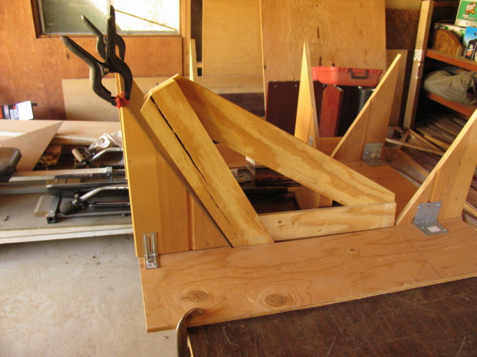
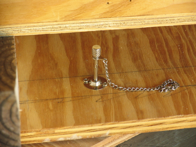
I had thought of making the gimbal pivot axis from a threaded rod that would span the width of the interior, and with nuts
attached on each side of the liner to prevent it from bending inward under a heavy load. Then I realized I could
attach the gimbal pivots to the box itself, as shown here. The pivot brackets are the familiar repair plates obtainable
at any hardware store, bent to a right angle. To determine the best positioning of the pivot points, I made a template of the cross-setion
of the pot sitting on the tray. I then experimented with different pivot locations on the liner side until I found
the one that best fit the expected maximum tilts for my latitude.
|
|
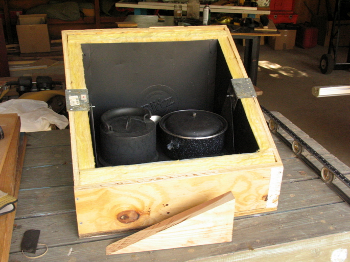 A kettle and my favorite cooking pot on the tray, each full of water to test the strength and rigidity
of the gimbal system. So far so good. I heat dishwashing water in the kettle.
A kettle and my favorite cooking pot on the tray, each full of water to test the strength and rigidity
of the gimbal system. So far so good. I heat dishwashing water in the kettle.
The wedge will be used to tilt the oven as the sun rises and sets.
|
|
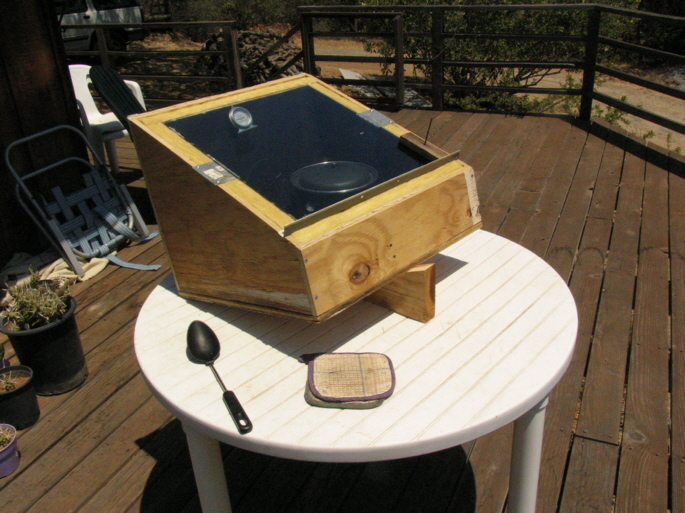
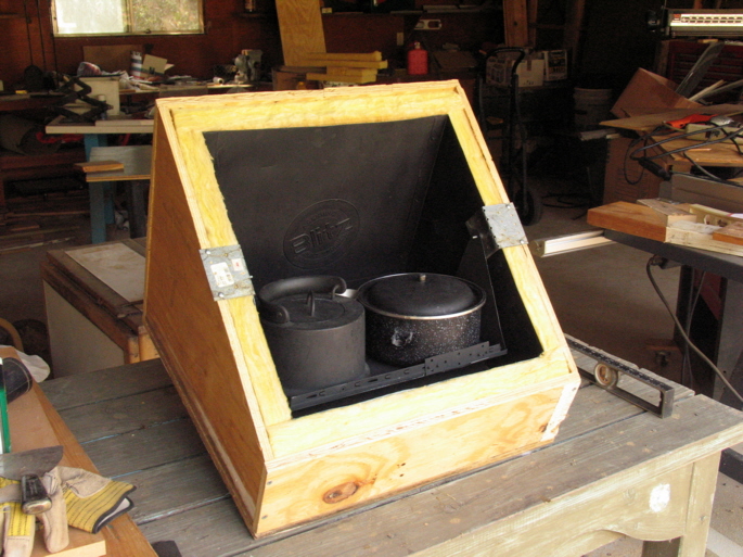 Morning tilt.
This position approximates the maximum "forward" tilt; the edge of the cooking pot is close to
where the collector plate will be.
The box also needs to be rotated through the day. For that motion, I will make a lazy susan, with a lock
against winds which can blow the box away from its proper orientation.
|
|
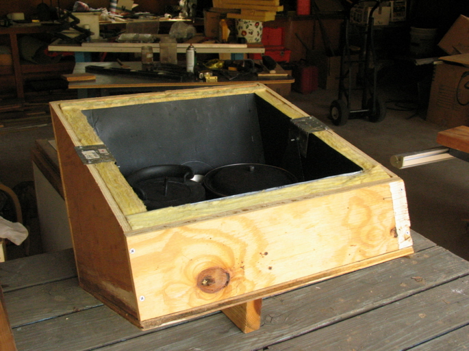 Noon tilt.
As the sun rises through the morning, the box is tilted backwards, passing through its horizontal position
until it reaches its maximum "back" tilt when the sun is highest in the sky. Here the position for
the summer solstice is approximated.
|
|
The next step is to design the reflector panel and collector module. This will be more complicated and
even unwieldy, but I think I have the basic idea in mind now. Stay tuned.
|
|
 Two days later.
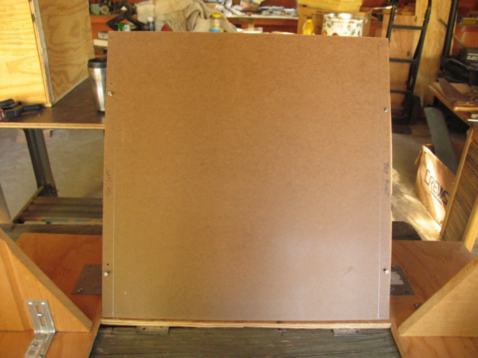
Again, several steps are represented. For the reflector base, I bought a sheet of 1/2" plywood, and cut a
"square" panel. It is larger than my 18-1/2" x 18-1/8" tempered glass collector by 9" on each side,
for reasons that will become apparent later.
I then centered the tempered glass collector plate on the panel, outlined it, and cut a hole just barely
larger than the collector. I am not skilled at making straight cuts with a lightweight saber saw, but
the opening will nevertheless serve nicely. On the bottom side of the panel I screwed on 4 small metal
tabs to keep the glass collector from falling into the oven. I made the tabs from lightweight metal repair plates
available at all hardware and home improvement stores. The tabs obstruct a negligible amount of sunlight.
Here the base is attached to the box, the collector plate is in place, my favorite cooking pot is
on the tray, and the box is tilted toward an imaginary morning sun. As it happens, the limit that the box
can be tilted because of the 9" extension of the base beyond the edge of the collector is exactly the point at
which the edge of the pot hits the glass. I thought I might have to cut a strip off of this front section of
the base.
|
|
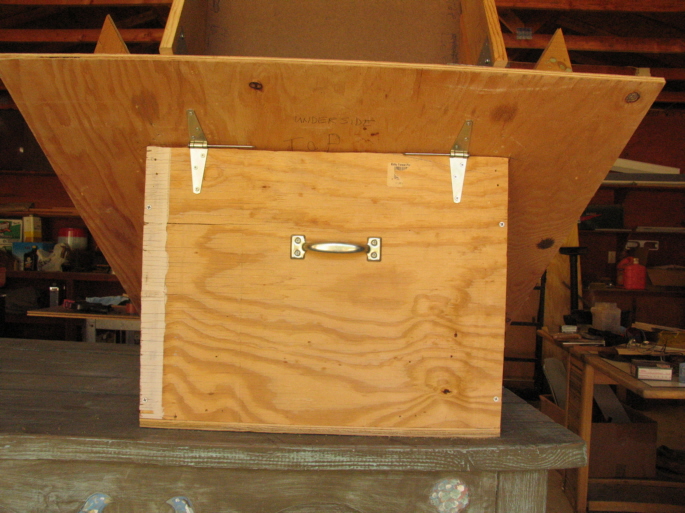
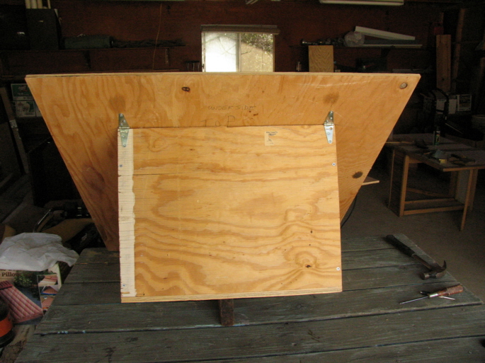 I wanted an easier way to get food in and out of the box, and hit upon the idea of hinging the reflector base
to the box. These two lightweight hinges should be enough for the maximum weight I anticipate
for the reflectors.
I wanted an easier way to get food in and out of the box, and hit upon the idea of hinging the reflector base
to the box. These two lightweight hinges should be enough for the maximum weight I anticipate
for the reflectors.
|
|
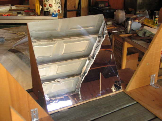
 It is clear that the hinged reflector base will be a very convenient enhancement.
The two light-colored "dots" near the side edges of the collector are recesses for the heads of the
screws that hold the gimbal pivot brackets in place. This allows the reflector base to rest snugly
on the edge of the box. An air gap the thickness of a screw head should not be a serious problem in the
summer, but in the winter it might let enough cold air in to slow the cooking process.
I will make a less clunky support for the raised base later.
Now comes the unwieldy part: securing the reflectors to the base at 30 degrees off the normal to the
collector. This will take a little head-scratching and experimentation, so it may be a few days before the next post.
|
|
 Next day, 4:35 p.m.
It occurred to me that I could probably use the box to cook in while I was making the reflector system.
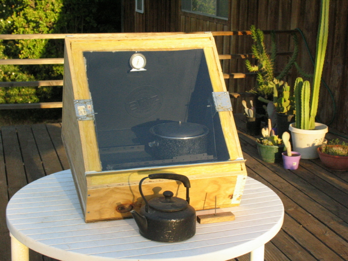
I added a bottom bracket to hold the glass in place and brought the box up to my deck. I filled my favorite
piot with water and oriented it toward the late afternoon sun.
The gnomon rests on the glass and shows that the box needs to be tilted further forward for maximum insolation. But
the box is already at maximum tilt. I definitely want to take advantage of the summer sun as late as 7 p.m at my latitude of 36-28 North,
so I will have to add a pivot point further back into the box to allow more forward swing before the pot hits the glass.
I am familiar with the low-sun orientation for this design, where the box rests on its "back", so to speak. But that isn't really
possible with the pivoting reflector base I'm making, and would be too much work for me in any case.
Hooking the tray hangers onto another pivot point is much easier than turning the whole unwieldy thing over.
The temperature inside the box went up to 200 degrees, and after an hour the water was fairly hot.
I'll soak 1# of beans tonight and see if they will cook thoroughly tomorrow.
|
|
 Next day — July 28, 2007, 07:00. (Henceforth I will use astronomical time.)
First light. Without reflectors, will the oven cook the beans? The box is at maximum forward tilt.
I'll put the half-filled kettle in the Solar Cookers International CookIt in case I need to add water to the bean pot
later in the day. I didn't want to slow the cooking process by adding relatively cool water, or by having the
kettle in the oven absorb heat that could go into the beans.
|
|
 13:00 PDT.
The sun is at or near its highest altitude. The themometer showed about 237 degrees. I continued to track the
sun until about 18:00.
|
|
 July 29, morning.
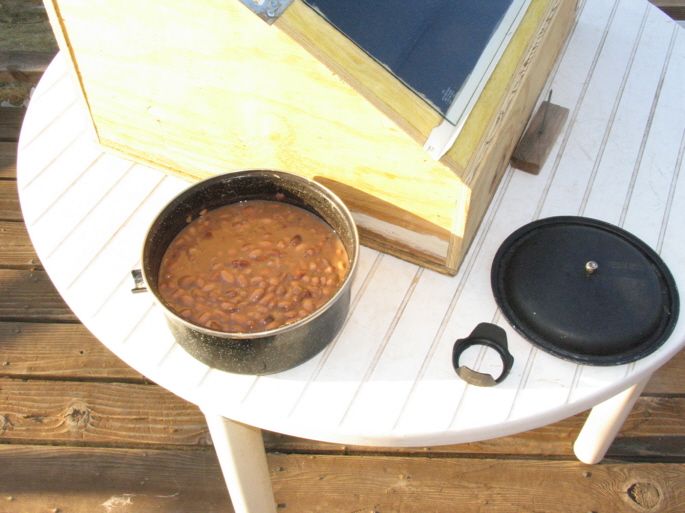
Success. I put the beans in the refrigerator overnite, and will now put them in pint jars and freeze them.
The beans cooked through, but were not as soft as they get with a hot oven. I did not have to add water for this batch.
|
|
 August 6.
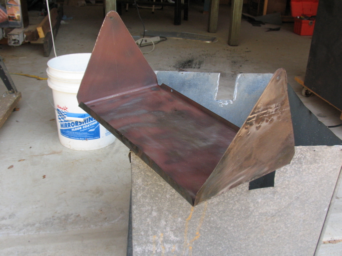
Again, several steps are represented here.
As it happened, after I removed the
square "doughut hole" for the glass collector plate, the lower section warped in the heat.
Thus I had to clamp the reflector base to my flat worksurface to insure the proper angle between
the reflector panels and the collector plate in that area. I'll fix that problem later.
The item resting on the table top is a template I made. The obtuse angle is precisely 120 degrees.
To the left of the template is the module for one reflector: two triangular supports,
a fairly stiff 18" x 18" square piece of composition board, and brackets to attach the reflector module to the
base.
The supports are 30-60 degree right triangles cut from scrap 3/4" wall siding (nominal — 11/16" actual). The top angle is 30 degrees, the sine
of which is 1/2. For an 18" hypoteneuse, this makes for a 9" side opposite the 30 degree angle.
For a solid support of the reflectors, I wanted to use
the full 18" hypoteneuse and the whole 9" "base"; thus the 9" on all sides of the the glass collector plate.
(The ideal reflector panel material is the composition board from which artists' easels are made —
the ones with the clamps to hold the canvas or paper. This board is thin and very rigid; it is perfect. But, I was not able to
locate a supplier of that material in 4' x 8' sheets, say, and I didn't want to buy several easels for this project. I welcome information
on where this composition board might be found.)
I clamped the panel to the supports at the top so I could (carefully) move the module around to position it exactly
at the edge of the collector opening, and at the same time determine whatever small adjustment might be needed
in fixing the support to the bracket so the reflector would be exactly 120 degrees off the plane of the collector.
(Later, I will glue reflective film to the composition board.)
I tried to be very precise in the cuts for the supports, but here the reflector panel on the left diverges slightly
toward the top. The vertical slot in the bracket will allow me to adjust this divergence. My first brackets were
made by bending flat Simpson repair plates (imagine a trademark sign here) to 90 degrees (see below). This
kind of bracket doesn't allow for adjustment, so I'll have to correct any divergence in the panel on the right
with shims along the edges of the supports.
|
|
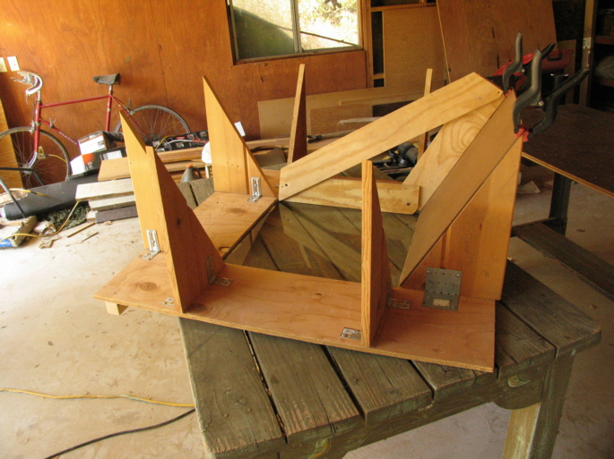 August 7.
The complete "skeleton", ready for the attachment of the reflectors to the supports.
The top of the reflector base is to the right. Along the width of the bottom underside of the base, I attached
a stiff wooden strip to remove the warp from the plywood there. The glass collector plate rests on its support
tabs, and the template sitting on it shows a virtually perfect fit with a reflector panel held in place by the clamps.
The next step will be to glue reflective film to the panels, and attach them to the supports with small
sheet metal screws, recessed. I will glue the film on to the panels before attaching them to the supports; the screw
head at the surface of the film can be covered with a small disk or square of reflective material.
|
|
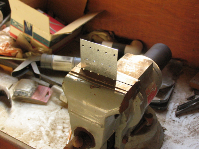 Someone might find this and the next two pictures useful.
Flat repair plate positioned for a bend at the center. The vice jaw surfaces are at 90 degrees
to each other.
|
|
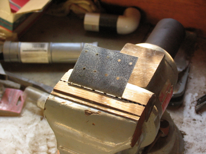
Begin the bend by pushing evenly across the width of the plate. Continue the bend
to the top of the vice jaw.
|
|
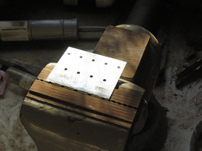
A few hammer taps finish the bracket. For my previous oven, I also made 120- and 150- degree brackets
from the same repair plates. They were used to attach the reflector panels directly to the
sides of the box.
|
|
 August 9.
A bare panel is temporarily attached to its supports. "Top left" and "top right" refer to the
top panel, left and right edges as one looks at the oven from the front. I later wrote the IDs on the
back of the panels at the "glass" edge: E.g.: "Right panel, glass." That so I would be able to match
up the pre-drilled panel and support holes.
|
|
The bare panel with a square of reflective film that will be glued to it. The roll of film is to the left.
I bought the film probably three years ago from
Nielsen Enterprises
Hydroponic Gardening/REFLECTIVE FILMS . I just now opened the box.
The film is 7 mil in thickness x 27 feet long x 56 inches wide. It was the stiffest film they had at the time, which
I wanted so that it would lay flat against the composition board more easily. The Nielsens now sell a 10 mill film,
"the cardstock of plastic mirror films." Sounds perfect. I am able to get three squares of film cut across the
56" width.
|
|
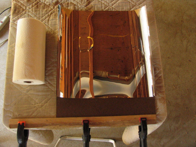 The setup for placing the film over the glued composition board surface. I will use 3M Super 77 Multipurpose Glue (spray).
I think that's what was recommended as a glue that would not dissolve the film.
The setup for placing the film over the glued composition board surface. I will use 3M Super 77 Multipurpose Glue (spray).
I think that's what was recommended as a glue that would not dissolve the film.
I am not famous for being
patient, and I did not build an elaborate mechanism for rolling the film out smoothly over the gluey surface
so as not to make ripples. I hoped I could use the film's natural curve and its natural stiffness
to my advantage. After spraying on the glue, I will set the panel with the edge close to, and parallel to
the clamped wood guide shown here. I will then carefully align the film above the
glued panel, holding it as a deep trough running away from me along the centerline of the panel. I will then carefully lay the centerline
of the film trough down on the gluey centerline of the panel and even more carefully guide the right side of the
film trough down onto the gluey side of the panel. I will then roll the paper towel roll shown here over
the film, pressing down so as to strengthen the bond. I will repeat the process for the left side of the panel.
|
|
 Success, pretty much. With care, the stiff film does indeed lay pretty flat against the composition board.
I mistakenly wiped the paper towel roll across the film, which left a band of micro-scratches on it.
Success, pretty much. With care, the stiff film does indeed lay pretty flat against the composition board.
I mistakenly wiped the paper towel roll across the film, which left a band of micro-scratches on it.
Here the now-reflective panel is attached to its supports with 4 4x3/4" sheet metal screws — two to each side.
I screwed the panels directly through the film, through which I actually drilled holes at the pre-drilled locations. This
so as not to damage the glue bond by punching a hole with a hammer and nail. The film is rather tough, actually. The excess
film at each edge of a panel is easily trimmed off with a very sharp knife.
|
|
 All the panels are reflectorized, and I'm replacing my hinges with sturdier ones. This
because, as usual, I made a mistake and placed two of the top support brackets right over the
screw holes for the original hinges. I'd have to use shorter screws or drill through the
brackets.
All the panels are reflectorized, and I'm replacing my hinges with sturdier ones. This
because, as usual, I made a mistake and placed two of the top support brackets right over the
screw holes for the original hinges. I'd have to use shorter screws or drill through the
brackets.
It worked out as I had originally planned, though. So I could separate the reflectors from the box for
easier moving or storage, I replaced the hinge pins with 4" 10d nails. I also added a handle on
the back wall to make tilting the box easier. I will have to add a handle to the front wall also.
|
|
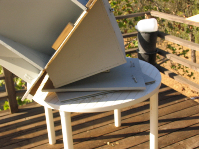
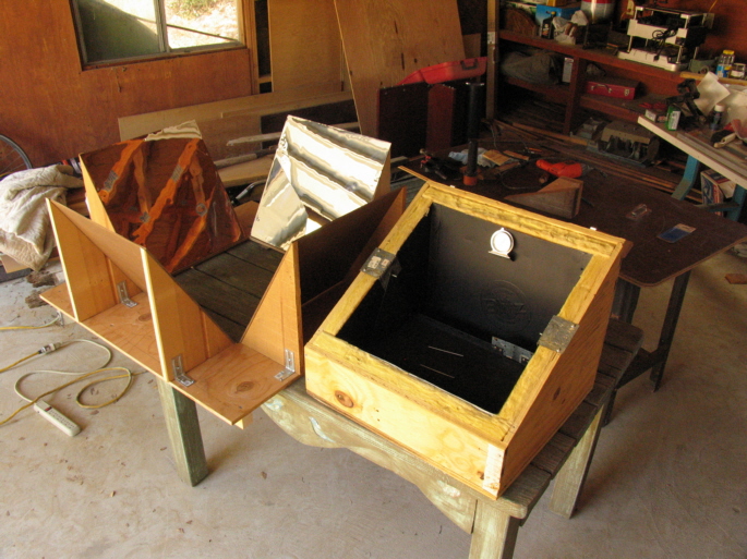 The reflector-base ensemble and the box are separated, waiting to be placed on my deck for
testing.
The reflector-base ensemble and the box are separated, waiting to be placed on my deck for
testing.
|
|
 I put the oven back together and set it facing the sun at 12:20. It is empty. The temperature began to climb immediately. At
13:09 the temperature reached 370 degrees. As I write this, it is 14:55 and the temperature is 375 degrees. Earlier there
was a very high, very thin cloud layer that reduced the insolation a bit. That cloud layer is now gone. There was also
some condensation on the underside of the glass, and the odor suggested volatiles being cooked out of the plywood and
maybe the paint. I'm confident that all harmful compounds will soon be cooked out of the oven.
I put the oven back together and set it facing the sun at 12:20. It is empty. The temperature began to climb immediately. At
13:09 the temperature reached 370 degrees. As I write this, it is 14:55 and the temperature is 375 degrees. Earlier there
was a very high, very thin cloud layer that reduced the insolation a bit. That cloud layer is now gone. There was also
some condensation on the underside of the glass, and the odor suggested volatiles being cooked out of the plywood and
maybe the paint. I'm confident that all harmful compounds will soon be cooked out of the oven.
The blemishes on the top panel are probably the result of less care in handling the film than I exercised for the
subsequent panels; some of them have the look of fingerprints. I'll put some beans in again tomorrow, and
make sure the glass and the films are clean.
|
|
 August 10.
I soaked 14 oz. of pinto beans overnight, added some salt and pepper, and 6 cups of water, and set the oven out facing the
rising sun at 07:00.
It is now 07:20, and the temperature in the oven is close to 212 degrees. As described above,
the oven is at maximum forward tilt. At this angle, and my latitude, the sun will not be normal to
the collector plate for another 2 hours.
|
|
 It's now 08:15, and the oven is about 270 degrees. By 09:30 it will reach 350 degrees, with the sun
pretty much normal to the collector plate. From then on, I will lower the back of the oven to track the sun as
it rises higher in the sky. I will make a lazy susan later, but meanwhile I rotate the entire table
clockwise around one leg.
It's now 08:15, and the oven is about 270 degrees. By 09:30 it will reach 350 degrees, with the sun
pretty much normal to the collector plate. From then on, I will lower the back of the oven to track the sun as
it rises higher in the sky. I will make a lazy susan later, but meanwhile I rotate the entire table
clockwise around one leg.
I didn't check to see when the water began to bubble, but by 11:20 the beans were cooked through, but not
to my taste texture-wise. (I like my beans pretty soft.) By 12:20 they were done to my satisfaction, and
I took them out. There was more water remaining than I like, so I'll start with less water per lb. of
soaked beans for the next batch. There is enough space between the upper edges of the box
and the glass to prevent condensation, at least for this configuration.
Thanks to a member of the Yahoo Solar Cooking group for making me aware that a heavy wind might raise the hinged top.
Now that I've raised and lowered the top a few times, though, I think it's probably heavy enough that I won't have to worry much
about any wind in which I would be inclined to cook in the first place. But, to be sure, I will add a latch system to
the top, which will also make it easy to tilt the oven backwards as the sun rises higher. I will also add
a hinged support to each underside of the top, which support can be set to hold the top up for hands-free access to
the oven interior.
The next step will be to fill in the corner triangles. I plan to make true conic surfaces for the corners, but to get cooking
efficiently quickly I'll probably make simpler plane triangles first. With those additions, I'm sure the oven will reach 400 degrees empty.
|
|
 August 19.
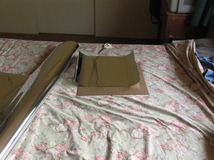
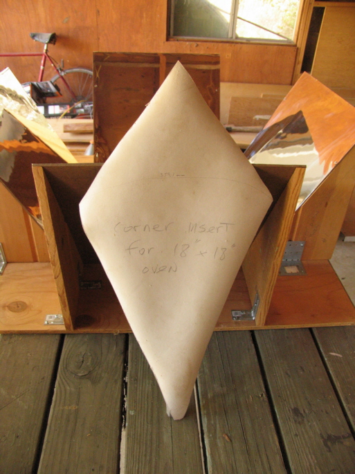
I decided to try true conical surfaces for the corners after all. These conical segments, like the plane reflector panels,
must also be 30 degrees off the normal to the collector plate. Since any semi-circle will produce a cone with a 60 degree vertex angle
when the two radii at the base of the semi-circle are joined, 1/4 of this conical surface of the cone,
attached tangent to each plane reflector, will be just this required 30-degrees off the normal to the plate. The linoleum
template shown here, with the 18" lower sides that will join the edges of the plane reflector panels,
is a quarter section of just such a cone, and will be the pattern for a thin sheet metal corner insert.
Ideally, the square reflector panels will meet at their bottom corners, and thus the bottom of this template would be
a 45-degree angle point. Here, the bottom is cut off a bit, reflecting a separation between the bottom corners of the
flat panels. This separation results from a combined sloppiness and also leaving myself a certain room to manuever.
Theoretically, we want to capture every ray of sunlight that can be reflected onto the collector plate, and thence into the oven.
Thus, the diamond shape of the template, with its peaked top, is determined by mapping the entire square of the collector plate
onto the conical surface of the corner insert. This mapping is necessary because each corner insert must reflect any ray that hits
it onto the collector, and all points of the collector must be "hittable" by some ray that hits the insert.
The distance from the
true bottom point of the template to the peak is the length of
the diagonal of the 18" square collector plate: 25.4558"/647mm. I suspect that the mapping function does not produce the straight
sides of the upper peak on the flattened quarter cone segment, but checking that surmise will take more work than I care to go to at
this point.
|
|
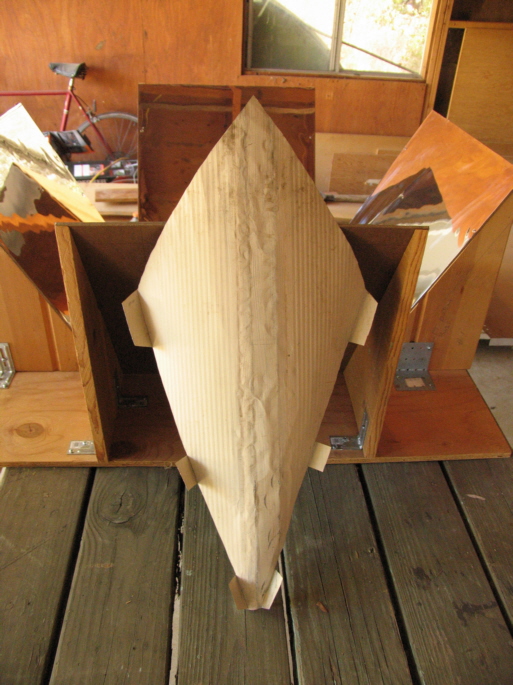 The corner insert here is the thin wall or roof of a storage shed that I dismantled. I pounded the
grooves flat, outlined the template, included tabs for attachment to the flat reflective panel supports, and carefully
bent it into a fairly close approximation of a conical surface over a table edge as I rotated it
around the narrow bottom angle. I hope that the same method I used to glue the reflective film to the
flat panels will work here as well.
The corner insert here is the thin wall or roof of a storage shed that I dismantled. I pounded the
grooves flat, outlined the template, included tabs for attachment to the flat reflective panel supports, and carefully
bent it into a fairly close approximation of a conical surface over a table edge as I rotated it
around the narrow bottom angle. I hope that the same method I used to glue the reflective film to the
flat panels will work here as well.
|
|
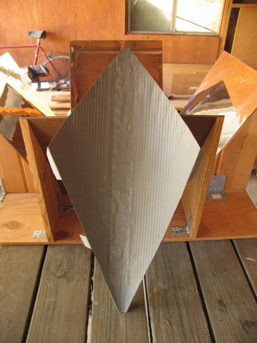 The "clean" surface that the reflective film will be glued to.
|
|
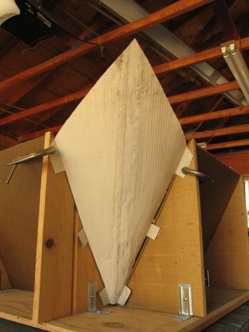 The mock-up. The sharp point at the top of the insert is just at eye level, so later I bent it down.
|
|
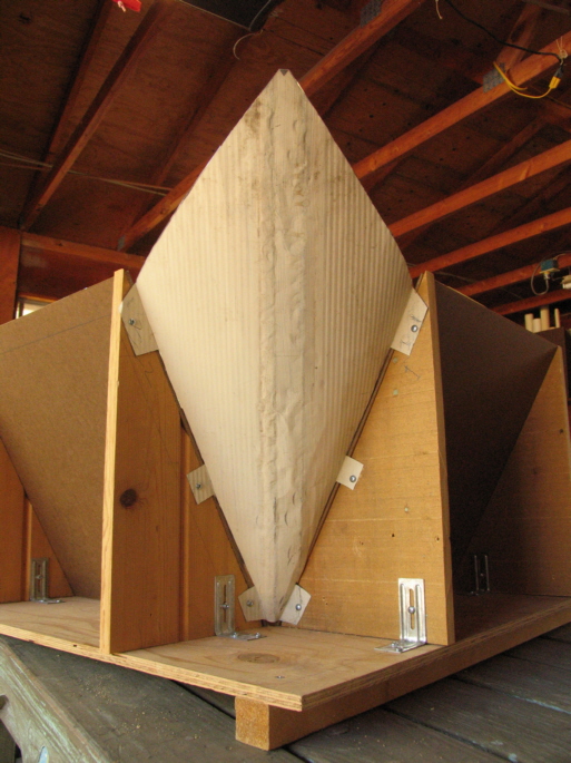
 The mock-up from the front. The angle of the insert is acceptably close to
the desired 120 degrees off the collector.
The mock-up from the front. The angle of the insert is acceptably close to
the desired 120 degrees off the collector.
|
|
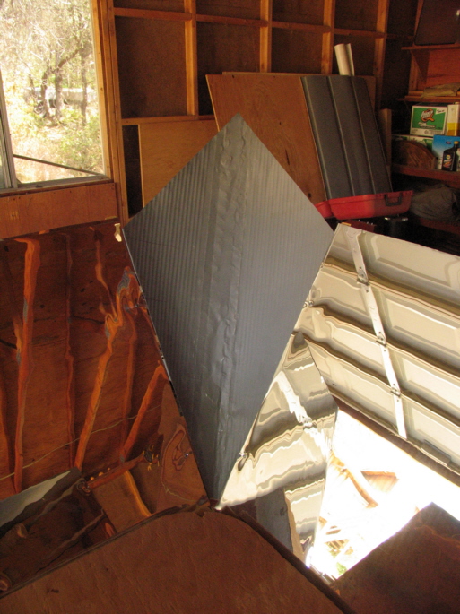
 The reflective film has been glued to the front surface, and the insert is now attached to
the supports. Here I use 8-18 x 1/2" self-drilling screws, but I always drill pilot holes nonetheless.
The reflective film has been glued to the front surface, and the insert is now attached to
the supports. Here I use 8-18 x 1/2" self-drilling screws, but I always drill pilot holes nonetheless.
|
|
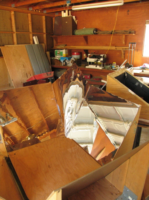 The insert with its reflective film. The area of this surface is about 175.35 square inches,
roughly 68.2 sq. in. larger than the typical plane triangle corner insert (without a peak) that most ovens
of this design use.
The insert with its reflective film. The area of this surface is about 175.35 square inches,
roughly 68.2 sq. in. larger than the typical plane triangle corner insert (without a peak) that most ovens
of this design use.
Considering that
the plane triangular insert is also at a non-optimal angle — less than 120 degrees off the
collector — I hope that using four inserts like this one will produce a hotter oven in spite of its
increased volume over my original creation.
The collector plate is in place, and I've protected it with three sections of foam covered by the plywood section
I removed to make the collector opening. If the collector plate were to be broken, replacing
it would be expensive — almost certainly over $100 for an 18"x18" piece of tempered glass.
Now, on to making the remaining three corner inserts.
|
|
The Finished Oven (More or Less)
|
|
 August 24.
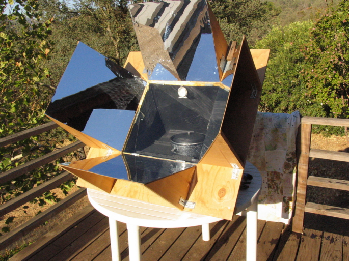
All the conical corner inserts are installed.
I set the empty oven facing the sun, but not normal to it, at 10:05 PDT.
It is now about 10:25; the sun is now normal to the collector plate. I'll now cook
a pot of beans.
|
|
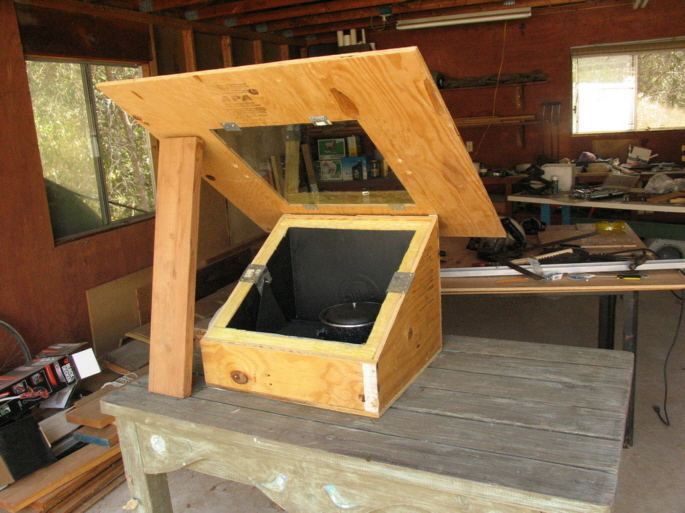
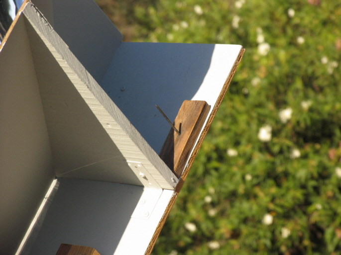
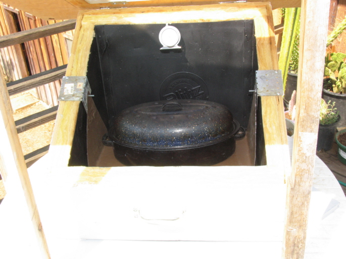
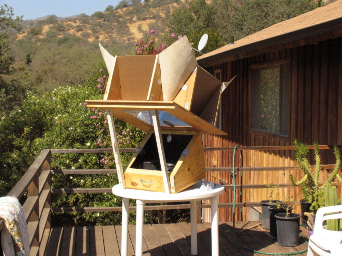 The lid is raised and supported for access to the oven interior, and the beans and rice are in place.
I will probably use these same sticks,
scavenged from my original oven, as hinged supports. I will attach hook and eye fasteners to hold the lid
down against a strong wind, but more to enable me to easily tilt the oven backward as the sun rises higher.
Visible here is the handle I attached to the front of the box for easy carrying when the lid is removed.
The 4d nails I am using for the lid hinge pins are too small for my taste, and I will look for a larger diameter nail.
|
|
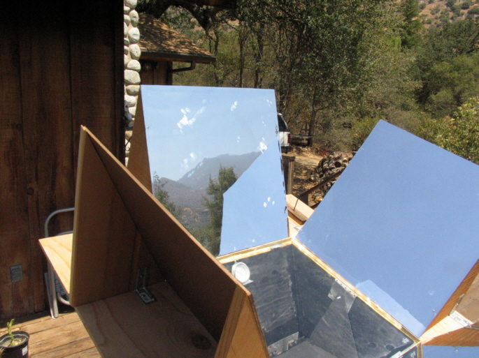
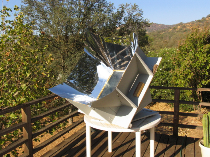
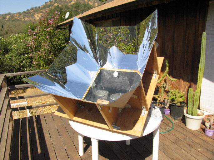 The oven and my future dinners.
The corner inserts do indeed reflect a lot of light into the oven, if not exactly to a ray's
theoretical destination. A slight push at even the peak area of the inserts causes light movement on the oven interior wall.
On the oven's efficiency in cooking two dishes: I put the food in about 10:30. At 12:13 the rice was cooked too dry, with some surface
grains crunchy. The rice was probably properly done at about 11:45 or 12:00.
But, most of it is ok, and I won't throw it away.
I had added 5 cups of water to 1# of unsoaked beans. Most of the water was now fully absorbed, some evaporated away,
and the water level was now at the top of the beans. I added 1-1/2 cups of water, which will heat up quickly enough.
Next time I will use 6-1/2 cups for unsoaked beans.
Next task: make a lazy susan for easy rotation of the oven.
|
|
 September 2.
The lazy susan. I do not show the actual, 12" diameter, ball-bearing race itself, which is between the two plywood panels.
Clear instructions for making the lazy susan are included with the race — available at most home-improvement centers —
and I assume the crafts- man/woman will have no difficulty in figuring it out.
I had a 27" x 47", somewhat warped plywood panel that I wanted to use, so I cut it in half for the top and bottom of
the lazy susan. The rectangular geometry limited the maximum radius of the holes around my "stop peg circle,"
so I drilled the holes in two arcs, one for the east-to-south orientation of the oven, the other for the
south-to-west orientation. (The "stop peg circle" is centered on the radius point of the lazy susan, of course.)
To create the "stop peg circle," I drilled two holes on the top panel, symmetrical on each side of the centerline of the
oven as it faced south — the tilt wedge is on this line — with a radius short enough that I would not come
too close to the edge of the bottom panel at the south-facing position.
I then oriented the
oven in its straight eastward position, and drilled through the right-hand top hole completely through the bottom panel.
I then rotated the oven a bit to the south, and drilled another hole. I proceeded thus until I came to the straight south orientation,
and drilled my last stop peg hole on the right-hand arc. I don't remember how many holes I drilled, but they were close
enough together that I can keep the oven pretty much directly facing the sun if I so desire.
I then repeated this process for the left-hand stop peg arc, drilling my last hole when the oven was facing straight west. (The
geometry of this lazy susan is rather ugly, but that's what you get when you use scrap material.)
|
|
 My stop pegs are $1.29 stops used to lock sliding glass doors. Here is the peg for the left arc.
Update of lazy susan construction, June 22, 2009:
I decided that the method described above was unnecessary, and also did not give me as much fine pointing control as I wanted. (Not that it makes that much difference as regards oven temperature.) In the future I will dispense with the holes and the peg stops, and simply drill a hole in the top panel of the lazy susan, into which a winged screw can be threaded snugly. I will probably grind a point on the screw tip. Simply turning down the screw against the base will suffice to keep the oven pointed correctly in any wind that does not blow the oven over.
|
|
 08:30.
The oven has been painted and sits on the lazy susan on my deck. I had taken several cans of very old
paint from a friend who had no way to get them to a toxic waste dump. I checked a couple of them out,
and found a white latex enamel undercoat and a gray latex exterior paint that would do just fine.
My deck faces directly south,
as does the base of the lazy susan here. (My apologies for a slightly fuzzy picture. My autofocus often
wavers when there are serious differences in depth in the frame and I can't always be sure I'm
getting a crisp focus.)
The unpainted block below the left reflector panel is a handle I made for easier carrying
of the detached reflector assembly. It's clear that I didn't use one of those software packages
that production managers use to lay out the work flow. (I'll probably never paint the block.)
I have not yet added a hook-and-eye latch to tie the hinged reflector assembly to the box in case of
wind and for easier tilting of the oven backward, and I may not bother. The lazy susan raises the box high
enough that I can reach the front handle for tilting, and I'm sure the reflector unit is heavy enough
to withstand any winds that I will encounter. If it is too windy, I just won't cook.
|
|
 The gnomon shows that the oven is "ahead" of the sun, meaning that the sun will need to rise
further, and travel a bit further west so as to be normal to the collector plate. I generally
keep the oven ahead of the sun.
The gnomon shows that the oven is "ahead" of the sun, meaning that the sun will need to rise
further, and travel a bit further west so as to be normal to the collector plate. I generally
keep the oven ahead of the sun.
|
|
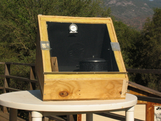
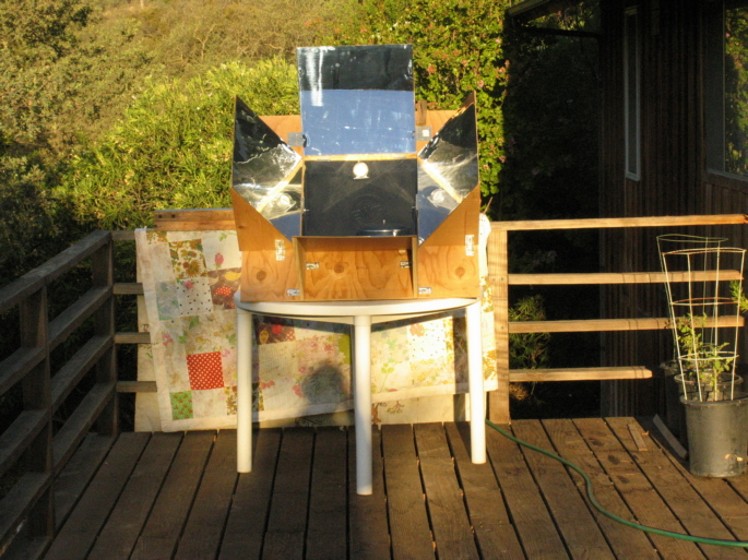
 Here it is in all its painted glory. Today I will not cook, but will simply see
how hot the empty oven will get.
Here it is in all its painted glory. Today I will not cook, but will simply see
how hot the empty oven will get.
10:45. The sun is normal to the empty oven, and the oven is at 462 degrees. Air temperature in the shade: 98 degrees.
(A bit on the cool side, actually. Again, I live in the foothills of the Sierra Nevada, at Latitude 36-28.)
13:15, just after the sun's peak elevation. I should have taken a picture of the thermometer at 10:45.
A high layer of cirrus clouds has covered the sun and reduced the temperature to just over 375 degrees.
That's all for today.
|
|
 September 4.
The streaks are from a morning cleaning of the glass collector plate. It had indeed
"fogged up" with some durable volatiles that continued to bake off during the few times I used the oven so far. I
first used used one of those red-and-yellow plastic brillo-type pads and window cleaner, but found that acetone was much more
effective.
September 4.
The streaks are from a morning cleaning of the glass collector plate. It had indeed
"fogged up" with some durable volatiles that continued to bake off during the few times I used the oven so far. I
first used used one of those red-and-yellow plastic brillo-type pads and window cleaner, but found that acetone was much more
effective.
I surmise that the these volatiles are at least similar in composition to those produced by the destructive
distillation of wood. I also assume that at some point all of these compounds will be baked out of the
wood and the glass plate will remain clear.
But again, let me remind visitors that they will be assuming the same risks that I assume if they proceed as I
plan to in the use of this oven. I make no claims as to the ultimate safety of any chemicals that are produced
by the oven and that might be ingested with the food cooked in the oven. If I go blind, I will make sure that a note to
that effect is placed at the top of this page.
|
|
 September 7.
In the bottom reaches of my kitchen cabinets I found a small roasting pan that was a perfect fit
for the oven, but a bit too wide for the tray I made. So, I decided to make a new tray out of a
microwave oven "skin" that I had saved. The tray's dimensions will be 8-1/2 deep " x 16-5/8" wide —
where "deep" refers to the tray's front-to-back dimension.
The skin was already factory-bent at right angles on two sides, with one edge bent up 1/2" at 90 degress, and the other edge flat.
Thus, one-half of my work in making the tray was done at the factory.
The skin is deeper and wider than the tray will be, so I will have to inscribe the outline for the tray bottom, the other edge
support, and the other side hanger support on the inside of the skin, and again cut the shape out with my aircraft shears.
To get the total width +
side hanger dimension I need, I will pound one of the factory 90-degree bends flat.
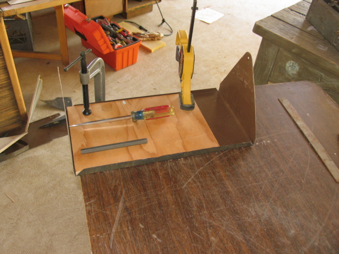
The view here shows the finished tray. (For the following, the visitor will have to use his or her imagination, because I do not show the
intermediate steps.) The skin is sturdy sheet metal, but needs bent edges on the long dimension to prevent sagging.
The original factory bends are shown front-to-back at the left and left-to-right at the back of the tray. I will create the bends at the
right and front.
The smudging on the upper right side hanger is where I pounded one of the factory bent sides flat. The visitor should imagine the
right side support hanger and the front stiffening edge shown here as being flat against the table. I then cut a
1/2" plywood "mandrel" to fit the shape of the tray bottom, placed it over the side support and stiffening edge bend lines, and clamped it
to the table as shown here. (Actually, at that point the right side support
hanger, as shown here, was hanging off the edge of the table, with the bend line and the plywood "mandrel" exactly over the edge
of the table. I then bent the side support hanger upwards by hand, and finished the right angle bend with careful taps
of a hammer.)
I then positioned the "mandrel" carefully along the stiffening edge bend line. To bend the edge upward, I crammed
the screwdriver shown here between the table and the edge and levered the edge upward as far as I could. I did this
along the entire width of the tray, making for a series of "scallops". I could not use the hammer to create a good
90-degree bend, so I tapped the edge into place using a drift I had made from the handle of a star drill. (Why I didn't
rotate the tray so the flat stiffening edge would hang over the edge of the table, and gently tap it into its right angle
postion I cannot explain.)
So, there you have it, as they say.
|
|
 Noon.
Noon.
The roaster on the tray. It is full of water, and the tray is clearly strong enough to hold it.
Before I paint the tray flat black, I will complete my normal Toxic Volatiles Bake-Off Procedure.
At 13:00 I checked the bake-off. The oven was at 450 degrees, and the interior was filled with nasty-looking brownish
smoke and who knows what even nastier toxic fumes. They roiled inside the oven and wafted out from the edges of the
collector plate.
The microwave skin exterior seems to be coated with some kind of tough film, which cannot easily be
separated from the metal. Perhaps this film is the source of
these copious fumes and smoke.
At 14:30 the smoke had abated a bit, but the bake-off was definitely still in progress. I called it quits at 15:30, and tomorrow
I will try to burn the coating off both sides of the
tray with a propane torch. Not the most environmentally friendly thing to do, but then, I doubt that there are many environmentally friendly ways
to remove most sheet metal coatings. I will try to hold my breath through the entire procedure. Stay tuned.
|
|
 September 9.
The tray after I burned off the exterior coating with a Mapp-Gas torch. (The surface of the hangar facing
the camera was the outside of the microwave oven.) This coating was a rather thick polymer that produced lots
of nasty black smoke — my bad. The ash was then easily scraped off with a wire brush. I don't know what the brownish
material that coats the inside wall of the oven skin is, but it does not burn off in quite the same way as did the
polymer. Nor did it produce the nasty smoke. I decided to trust that I will not die
if I leave most of it on the tray.
Here the tray has been rubbed down all over with 400 grit wet emery paper, in preparation for the standard coat of
flat black barbecue paint. After painting the tray and letting it dry, I again did my standard Toxic Volatiles Bake-Off Procedure.
(On the 7th, even after I had taken the tray out because of the copius smoke, I noticed oily condensates
forming on the inside glass surface. But, I personally will take my chances with the oven after I see that the glass remains
clean after a normal day in the sun.)
Future posts to this page will likely not contain any interesting new "technology," but rather just small enhancements: maybe a
dust cover, utility cart, etc.
Or, maybe if I actually do die from poisoning and
my kids post my obituary here as a warning.
Finally, I will not use a microwave oven skin in the future unless I can
easily remove its coating in an environmentaly friendly manner.
|
|
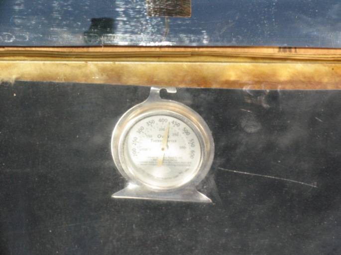
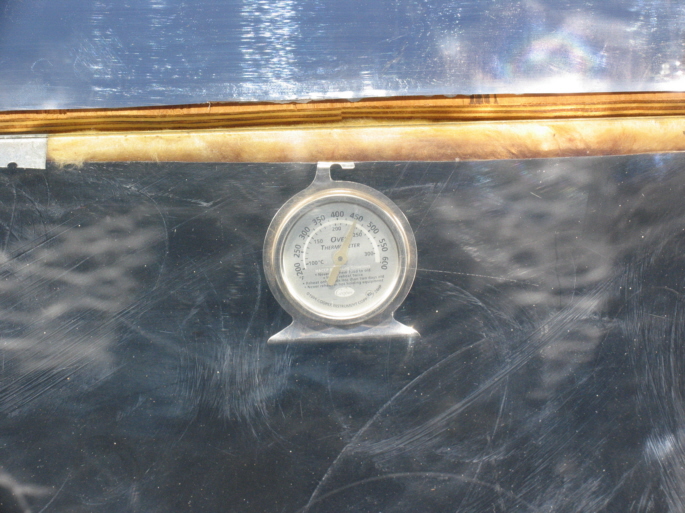
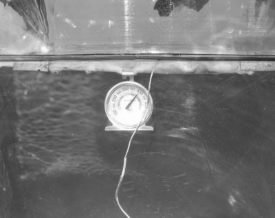
November 7.
It is 11:30, Pacific Standard Time, the sun is near its highest elevation, and the
oven is exactly normal to the sun. The day is cloudless but rather hazy.
The oven is empty. In the left photo, the dial thermometer, which is in physical
contact with the hot metal oven liner, shows 450 degrees. The chord is
connected to the digital meat themometer probe, which I placed in the oven so that it would not
be touching, or be too near, any metal surfaces.
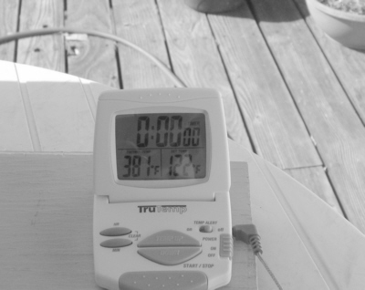
The right photo shows the greatest actual air temperature as measured by the probe after giving the
oven time to reach its maximum — 381 degrees. Assuming that the digital thermometer is accurate, it appears that
at this time of the year, and under such insolation conditions as today's, the air temperature in
an empty oven will be roughly 70-80 degrees lower than shown by a dial thermometer hanging on the back
metal liner.
Immediately after taking these pictures I placed a tray of brownies in the oven. The interior air temperature
went down immediately, and over a 40-minute period rose to 324 degrees when the brownies were done. The dial
thermometer then showed 400 degrees. Later, I found that a dial thermometer placed on the tray next to the pot
gave the same reading as the digital thermometer. I now use the dial thermometer on the tray exclusively.
|
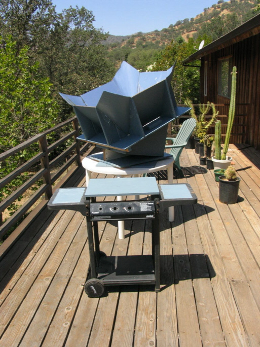
June 17, 2009.
The oven is newly painted with leftover paint from a friend. Shown too is my handy utility cart, made from a
discarded barbecue frame. The oven is empty, and my dial oven thermometer shows 400 degrees.
May 15, 2011.
A visitor asked what the total oven ensemble weighed. Here it is, as good as my bathroom scale can measure it:
Box: 26#
Base: 20#
Glass plate: 3.5#
Reflector module without glass: 27.5#
Total: 77#
|
|
 Click here to join the Yahoo SolarCooking Group.